 rotary jointsrotary joints
Search the whole station
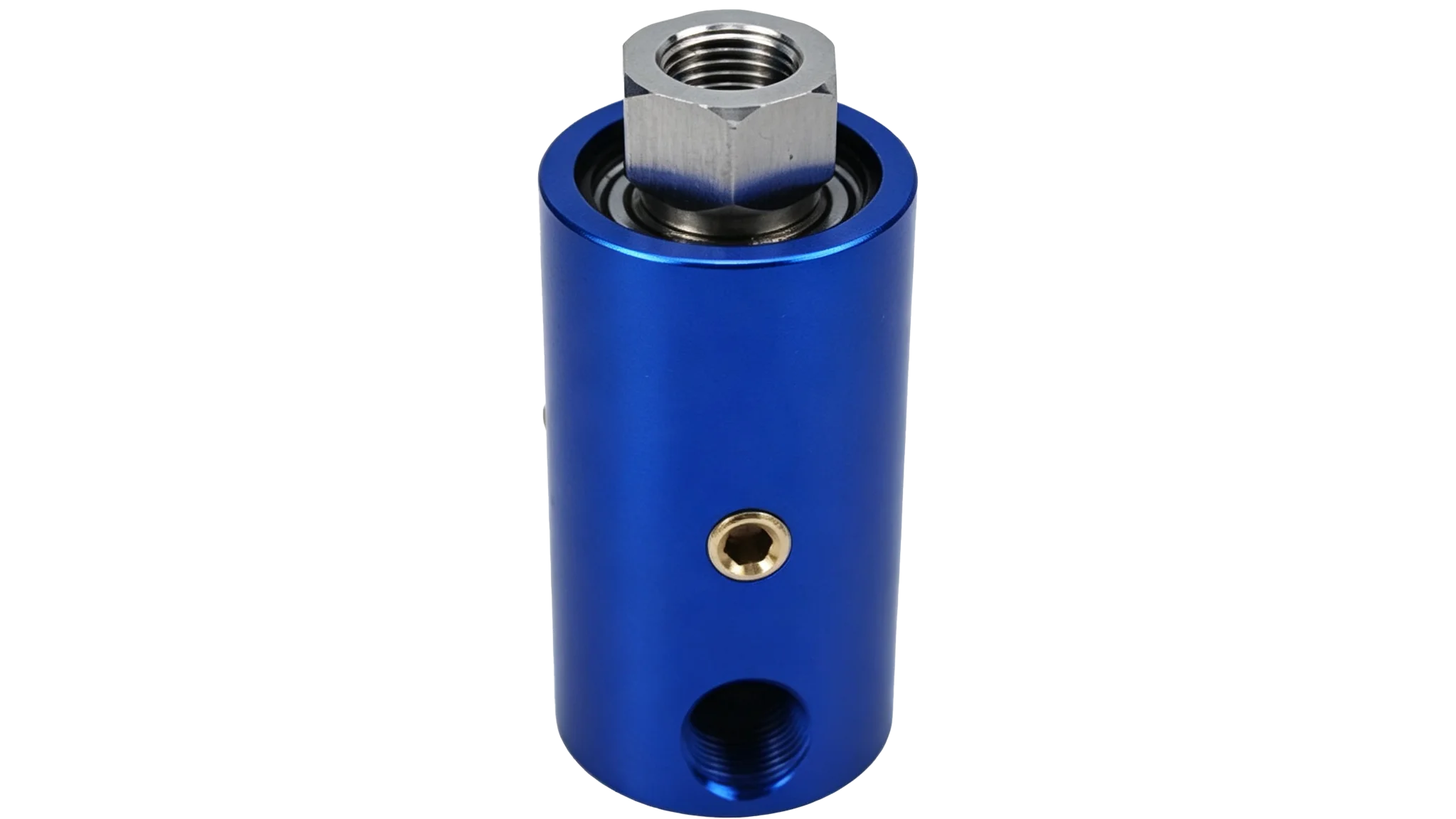
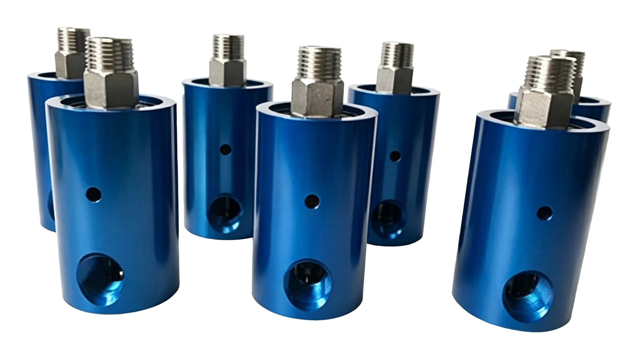
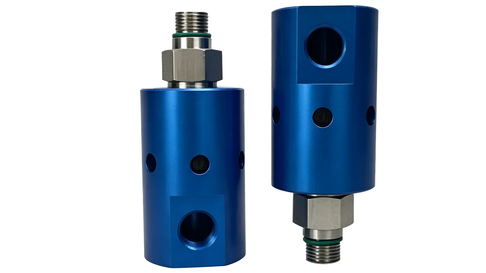
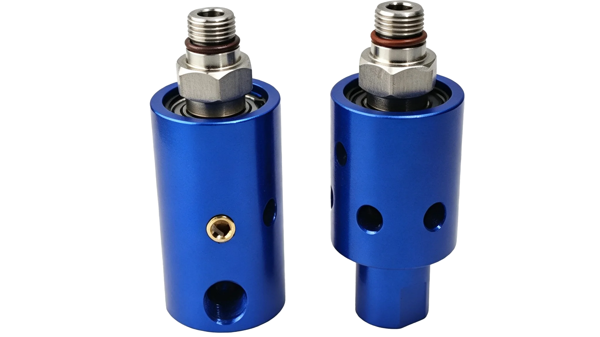
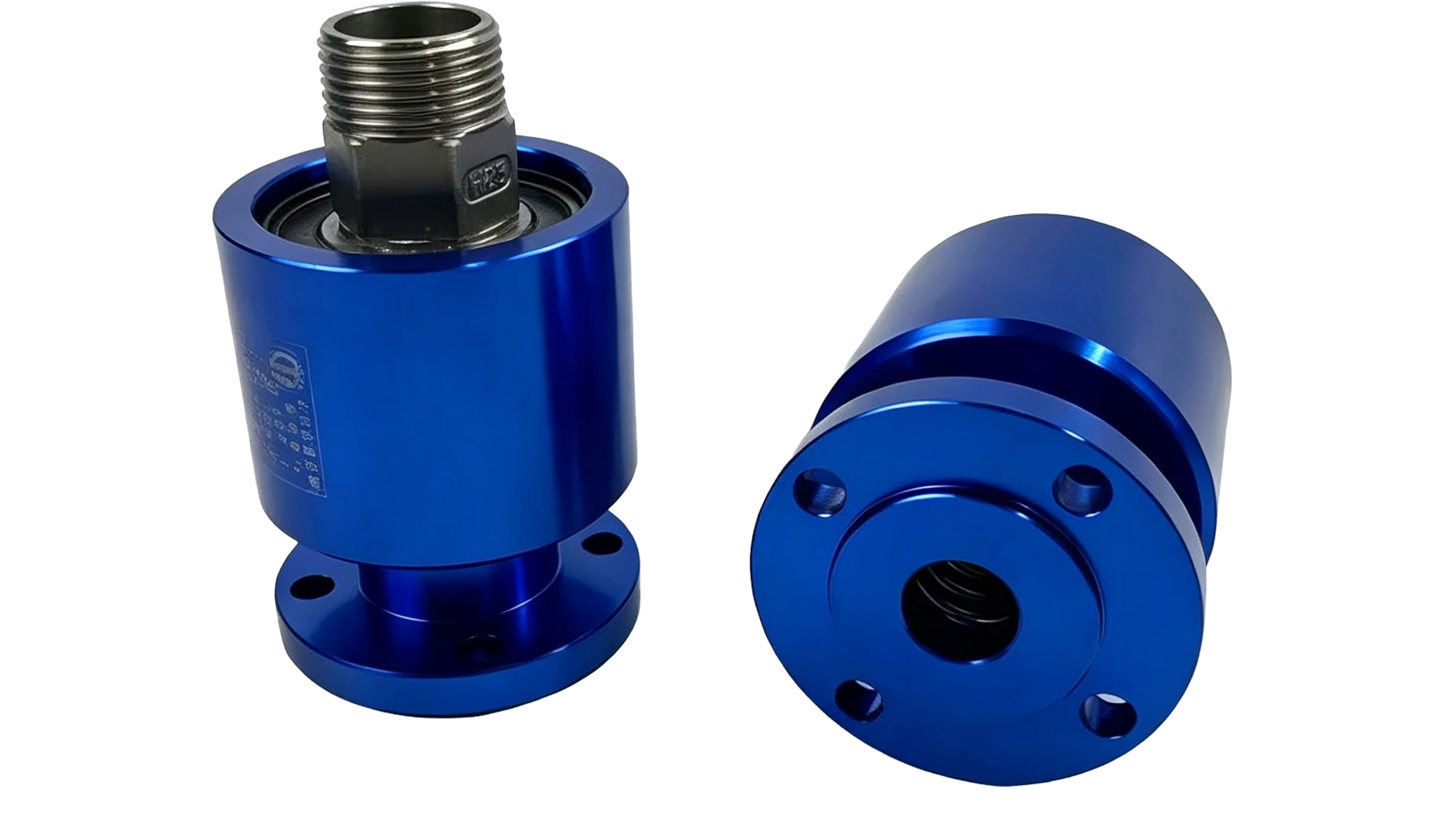
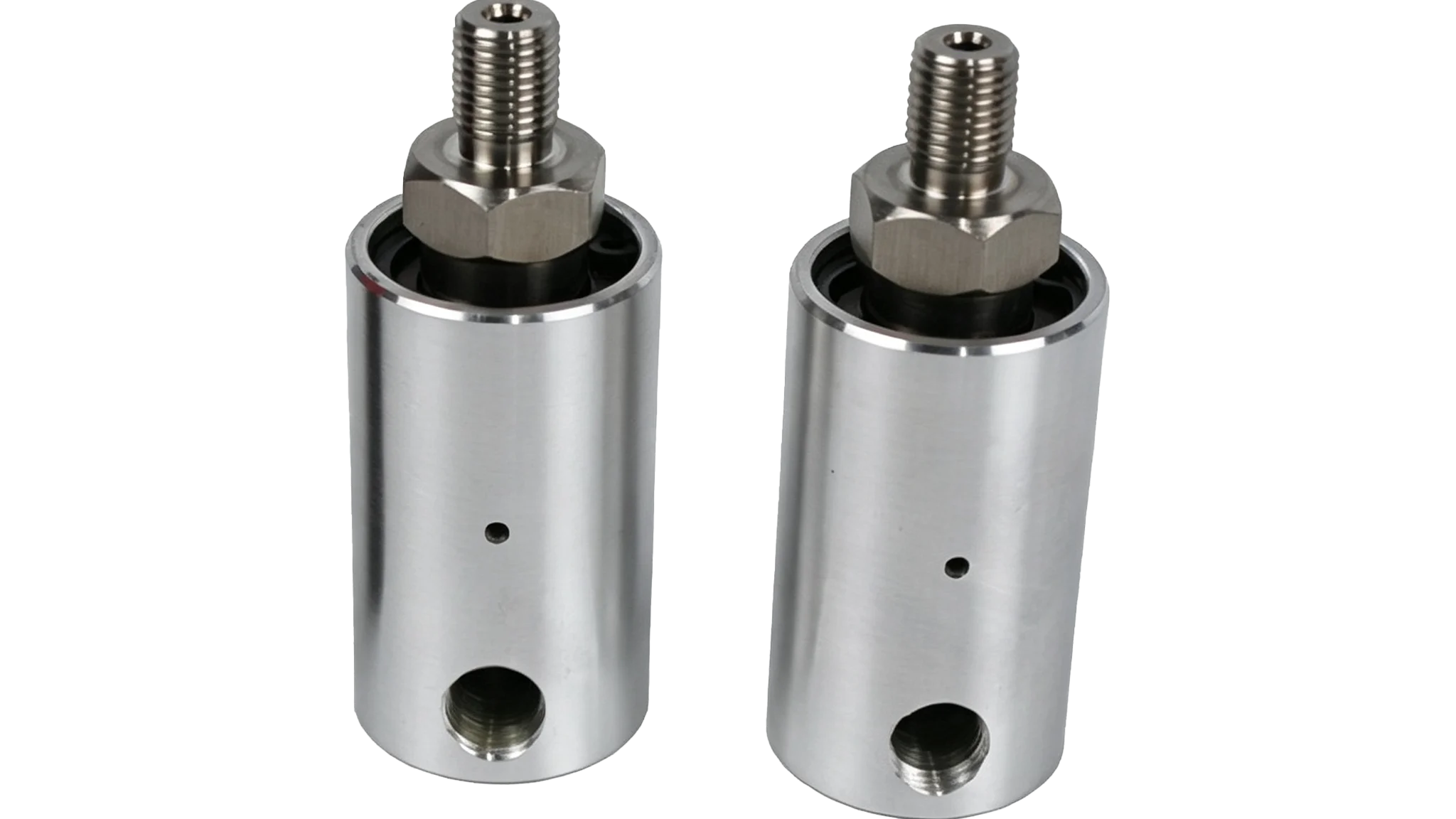
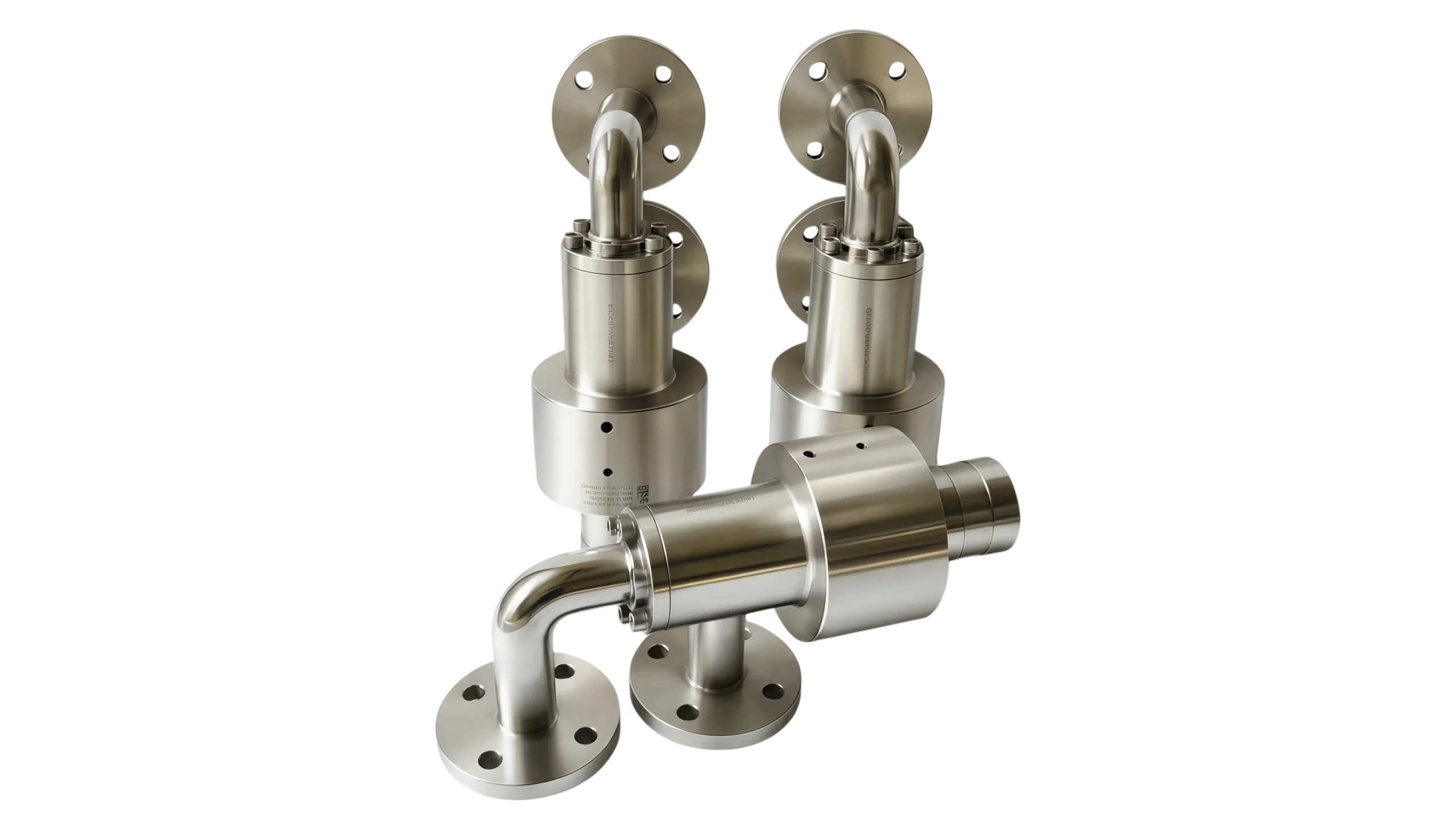
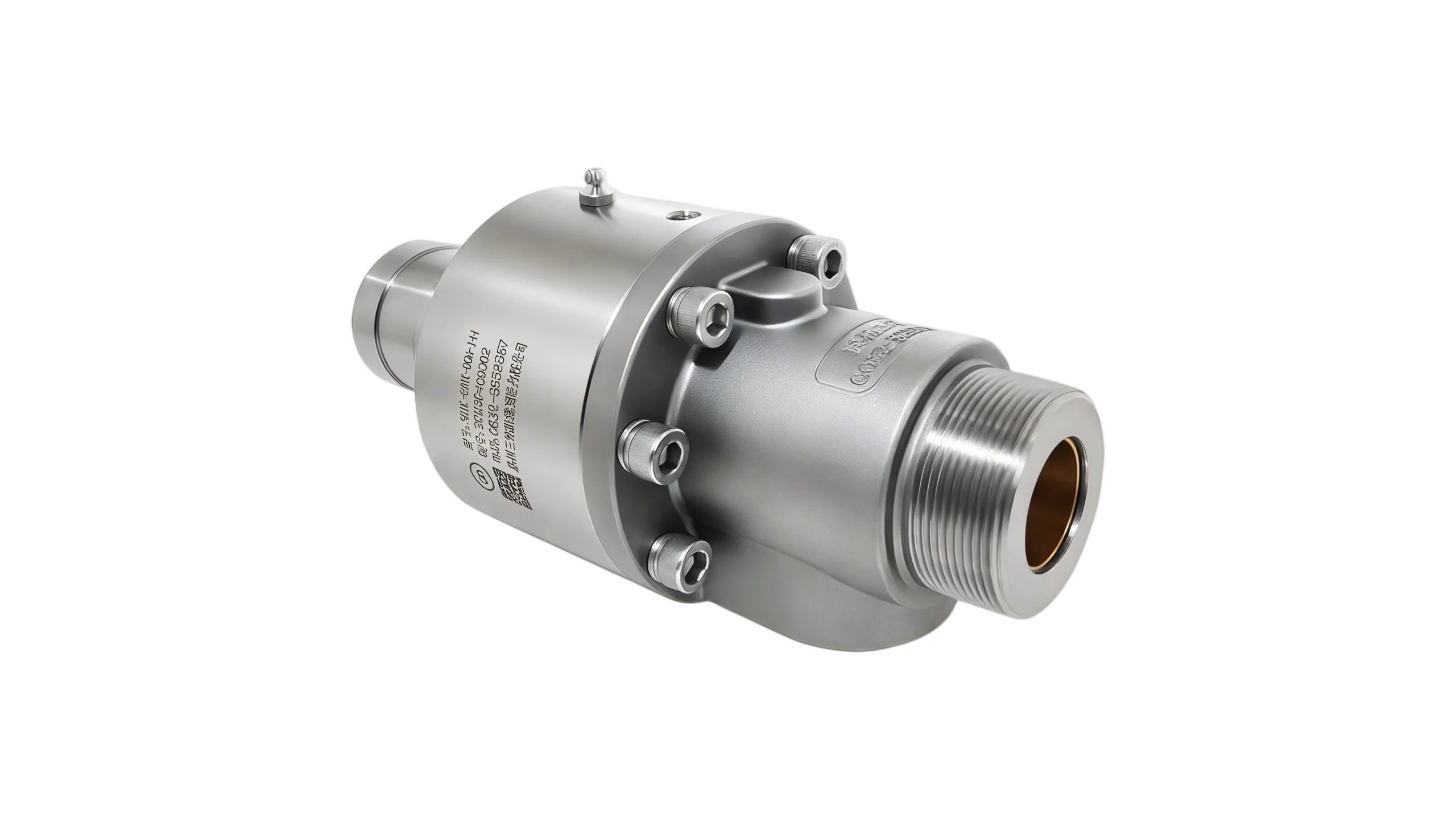
High pressure direct rotating joint is a mechanical sealing device with two coaxial lines at both ends, used for leak free transmission of high-pressure fluids (water, oil, steam, etc.) under dynamic rotating conditions. Its core features include straight passage, low pressure loss, and pressure resistance
Structural characteristics of high-speed rotary joints: corrosion-resistant materials, special design that does not damage the joint even under limited conditions, sealed rolling bearings do not require lubrication for life, balanced sealing load and wear are reduced to a minimum, reducing torque, sealing materials have self-lubricating properties, and spring components are located on the outside of the fluid channel, thus reducing pressure loss, avoiding particle retention in the medium, and overall improving fluid quality.
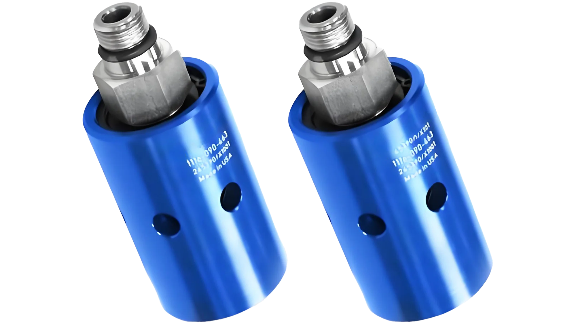
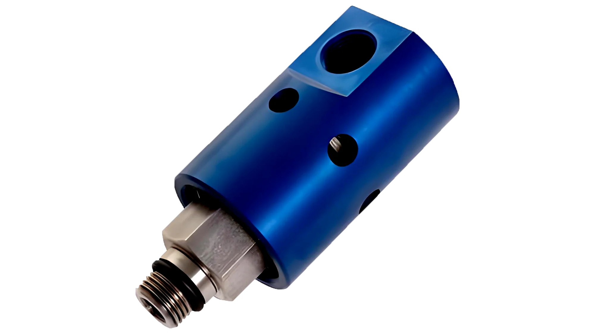
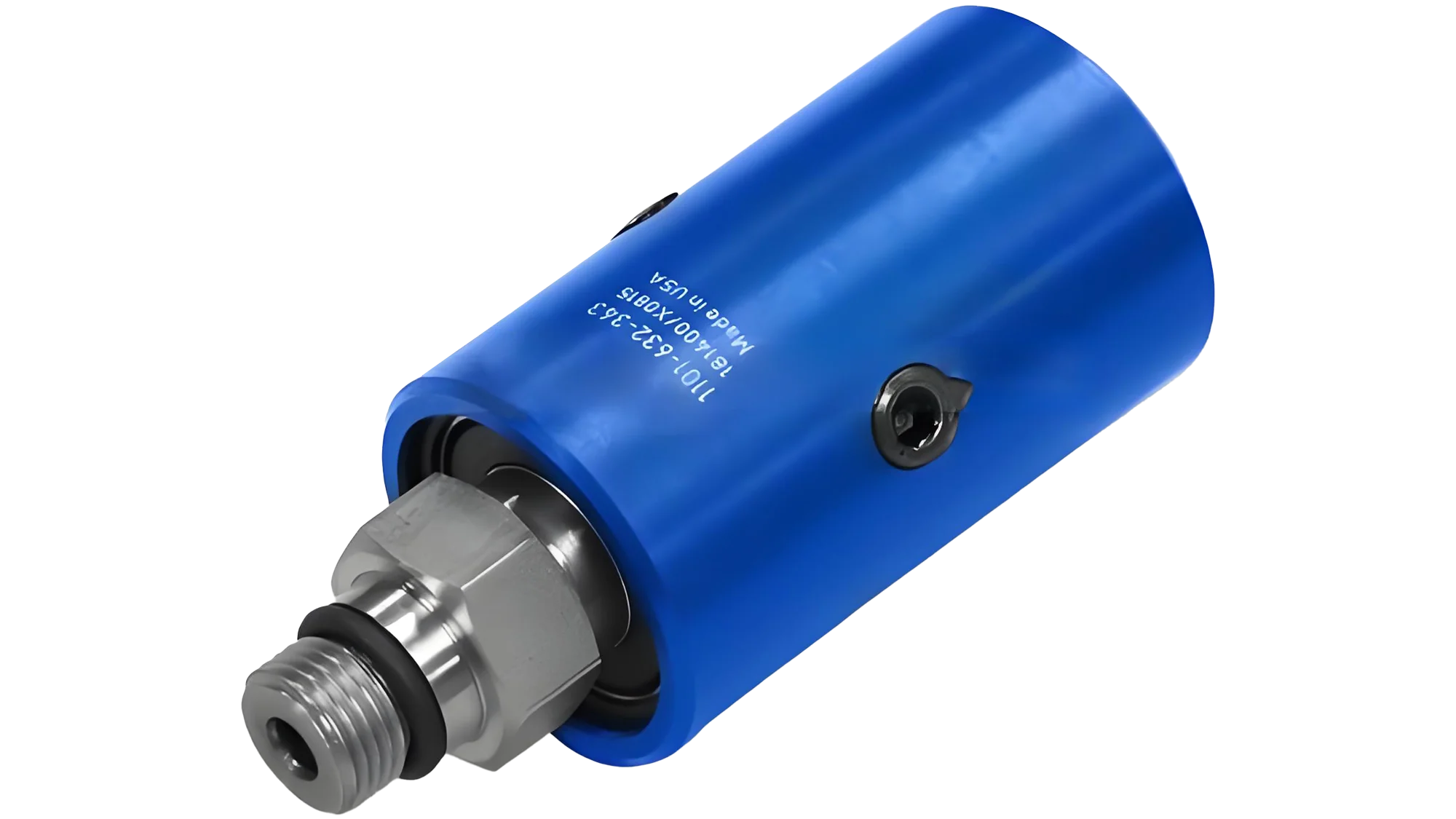
Hydraulic high-speed pneumatic rotary joint is suitable for flexible applications in water, hot oil, and steam
Stainless steel outer tube is corrosion-resistant and has a longer service life
Complete and uniform flow design with minimal pressure loss
Two precision imported bearings support to ensure long-term trouble free operation
The balanced mechanical seal design reduces the wear of the sealing surface caused by the sealing load, greatly extending the service life
Select materials for the sealing mating surface according to customer needs
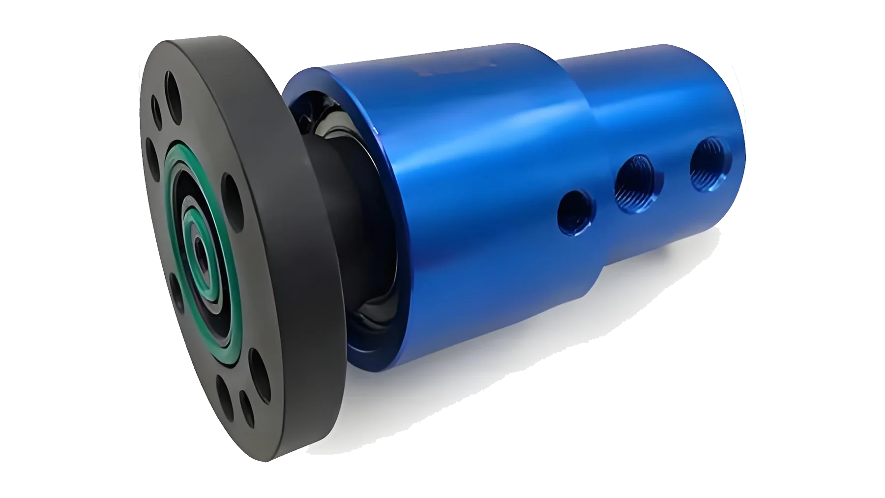
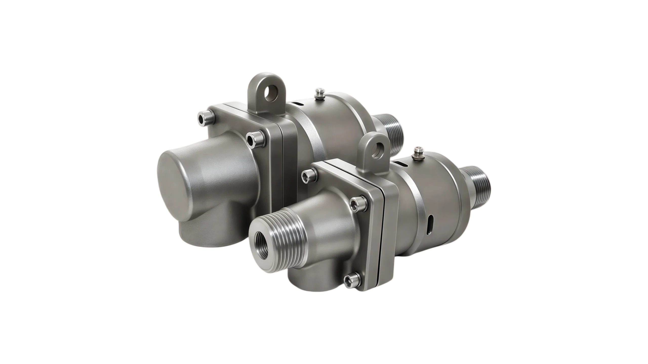
The external pipe has threads or quick change flange connection method, which has strong installation flexibility
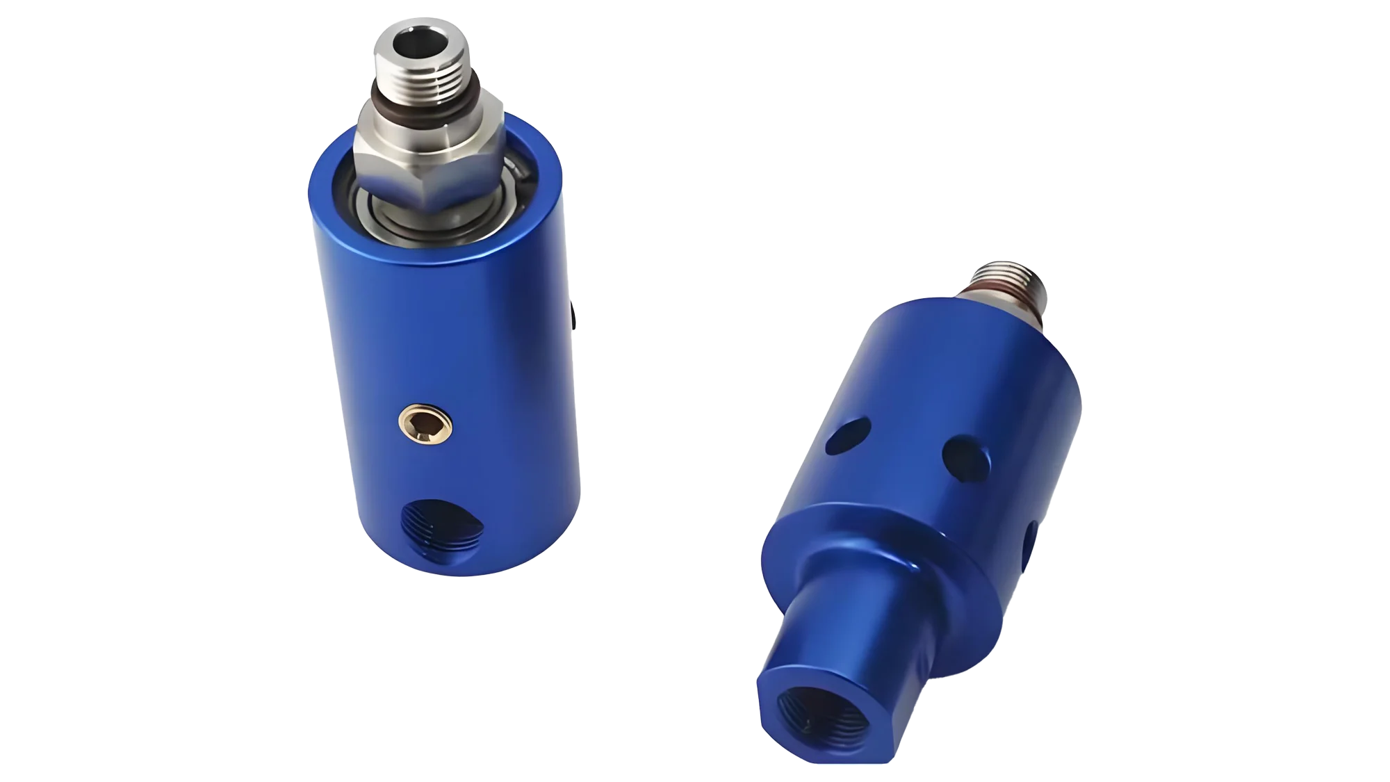
The shell is equipped with oil injection nozzles for reasonable maintenance of bearings, extending their service life
The shell is equipped with observation holes to observe leakage and wear conditions for timely maintenance measures
The shell material selected for the SD rotary joint is copper alloy shell for the water-based type, and aluminum or aluminum alloy with copper shell for the air type. The advantage is that it has good heat dissipation performance under high-speed transmission, but the disadvantage is that it is prone to deformation, which brings inconvenience to maintenance. Aluminum alloy shell, equipped with imported SKF and TIMKEN bearings, impregnated graphite rings, 304 stainless steel silicon carbide shafts, and wear-resistant fluorine rubber O-rings suitable for high-speed rotating equipment, making it more wear-resistant and have a longer lifespan
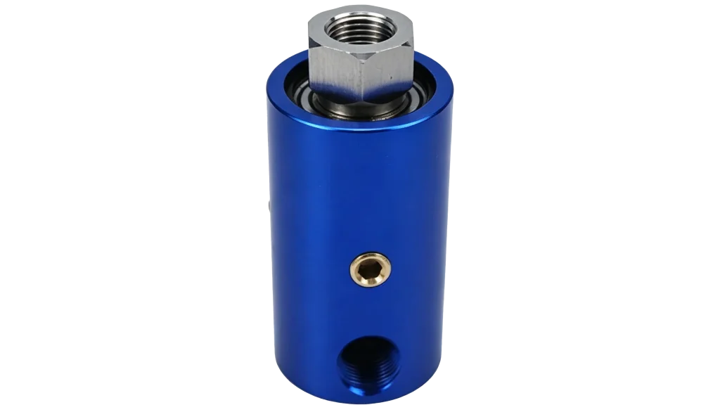
Modern engineering frequently encounters a complex, unavoidable challenge: how do you safely and reliably transfer immense amounts of electrical power from a stationary structure to a continuously rotating one? Whether you are designing the next generation of offshore wind turbines, advanced medical imaging equipment, or heavy-duty industrial excavators, the physics of transferring high voltage across moving boundaries is incredibly unforgiving.
Standard static cables will quickly twist, fray, and snap under continuous rotation. Traditional low-voltage slip rings, while useful for basic signals, simply cannot handle the extreme electrical stress of megawatt-level power without catastrophic failure. This is where the high voltage direct rotating joint comes into play.
A high voltage direct rotating joint is a specialized electromechanical device engineered specifically to transmit high-potential electrical power across continuous 360-degree rotational interfaces. Unlike a standard high voltage connector that simply locks two static cables together, a rotating joint must maintain perfect electrical continuity while its internal components spin at varying speeds.
In this comprehensive guide, we will explore the intricate world of rotating high-voltage systems. We will dive deep into advanced engineering concepts, explore various rotating electrical power transmission methods, and outline actionable strategies for selecting, installing, and maintaining these critical components.
To understand the value of a high voltage direct rotating joint, we must first look at the core mechanics of how power is bridged across a physical gap. At a fundamental level, rotating joints consist of a stationary block (the stator) and a rotating block (the rotor). Conductive pathways span the gap between these two components, typically using specialized brushes, liquid metals, or advanced contactless technologies.
When dealing with low voltages, the engineering margin of error is relatively wide. However, when you introduce high voltage—often ranging from a few kilovolts (kV) to tens of kilovolts—the entire dynamic changes. The physical separation between the conductive elements must be meticulously calculated to prevent electrical discharge, and the materials must withstand both intense mechanical friction and high electrical stress.
One of the primary challenges engineers face is managing rotational speed and voltage stability. As the rotor spins faster, centrifugal forces act upon the internal contact mechanisms. If traditional spring-loaded brushes are used, high speeds can cause microscopic lifting or “bouncing” of the brush off the conductive ring.
In a low-voltage system, a microsecond of lost contact might just drop a data packet. In a high-voltage system, that same micro-loss of contact forces the electrical current to jump the microscopic air gap, creating a destructive arc. This arcing not only degrades the power quality, leading to severe voltage instability downstream, but it also physically melts and pits the conductive surfaces. Therefore, high-quality high voltage solutions utilize heavily engineered tensioning systems, multi-point contact brushes, or liquid metal interfaces to ensure the physical connection remains absolutely constant, regardless of the RPM.
When electricity is pushed at high pressures (voltages) through a rotating interface, it naturally seeks the path of least resistance to the nearest ground. Preventing the current from escaping its designated pathway requires robust insulation strategies.
The foundation of any safe high-voltage rotating device is its dielectric material. The dielectric strength requirements for power slip rings are exceptionally stringent. Dielectric strength refers to the maximum electric field a material can withstand under ideal conditions without undergoing electrical breakdown and becoming electrically conductive.
In a rotating joint, the dielectric barrier must separate the high-voltage channels from one another, as well as from the grounded outer housing. Engineers must calculate the insulation breakdown voltage in rotating interfaces by taking into account not just the nominal operating voltage, but the maximum potential surge or spike the system might experience. If a system operates at 10kV, the insulation breakdown voltage must typically be rated for at least 20kV to 30kV to provide an adequate safety margin against transient overvoltages.
To achieve these high breakdown voltages, manufacturers employ various insulating mediums. The debate between liquid versus solid insulation for electrical swivels is a common one in electromechanical design.
For most modern industrial applications, advanced cast epoxies and solid polymers are the preferred choice, striking a balance between longevity, safety, and maintenance-free operation.
A rotary joint is a sealing device that connects stationary pipelines and rotating equipment, achieving leak free fluid transmission under 360 ° rotation. It allows fluid media to flow smoothly between fixed pipelines and rotating machines, and is a key component in industrial equipment
F90 swivel unions Transporting equipment components from a fixed pipeline system to high-speed rotating or reciprocating motion
Q32 swivel unions
JD40 rotary joint is a key sealing component in industrial fluid transmission systems, usually referring to a rotary connection device with a diameter of DN40 (or corresponding British caliber). As a transitional sealing device that transports fluid media (such as water, steam, hydraulic oil, thermal oil, compressed air, etc.) from static pipelines to dynamic rotating or swinging equipment